The cocotb regulator Testbench
New in version 1.5.
This is the testbench test_regulator for the design regulator showing
how cocotb can be used in an analog-mixed signal (AMS) simulation.
Note
The analog probe module used in this testcase is currently only implemented for the Cadence Incisive and Xcelium simulators (with the AMS option available). Help is appreciated to provide equivalent modules for other simulators.
Overview Schematic

The Design
The design i_regulator consists of a trimmable regulator model written in Verilog-AMS
(instance name i_regulator_block), and load resistor (instance name i_resistor).
module regulator(input       vdd,
                 input [3:0] trim,
                 output      vout,
                 input       vss);

  regulator_block
    #(.vout_abs  (3.3),
      .trim_step (0.2))
  i_regulator_block
    (
     .vdd  (vdd),
     .trim (trim),
     .vout (vout),
     .vss  (vss)
     );

  resistor
    #(.resistance (100))
  i_resistor
    (
     .p (vout),
     .n (vss)
     );

endmodule
The regulator block itself is modeled as shown below:
`include "disciplines.vams"
`include "constants.vams"

module regulator_block(vdd, trim, vout, vss);

  input signed [3:0] trim; logic trim;
  inout vdd; electrical vdd;
  inout vout; electrical vout;
  inout vss; electrical vss;

  parameter real vout_abs=3.3 from (0:inf);  // must be > 0
  parameter real trim_step=0.2 from (0:inf);  // must be > 0

  real trim_volt;

  always @(trim) begin
    trim_volt = trim * trim_step;
    // $display("%m: trim=%0d --> trim_volt=%f", trim, trim_volt);
  end

  analog begin
    // TODO: limit voltage to vdd/vss
    V(vout, vss) <+ transition(vout_abs + trim_volt, 0, 20p);
  end

endmodule
The Testbench
The testbench consists of both an HDL part and a Python/cocotb part. While having HDL as part of the testbench is not common with cocotb, it is perfectly possible.
The HDL part of the Testbench
The testbench HDL part is written in SystemVerilog and instantiates the design described above
as i_regulator.
It also contains a probe module for analog values as instance i_analog_probe —
imagine this being a multimeter that you quickly connect to different nodes in the design,
measuring either voltage or current.
import nettypes_pkg::*;

module tb_regulator;

  voltage_net vdd, vss, vout;
  real vdd_val, vss_val = 0.0;
  logic signed [3:0] trim_val = 0;

  assign vdd = vdd_val;
  assign vss = vss_val;

  // the design
  regulator i_regulator (.vdd  (vdd),
                         .trim (trim_val),
                         .vout (vout),
                         .vss  (vss)
                         );

  // the "multimeter"
  analog_probe i_analog_probe ();

endmodule
The probe module can capture voltage and current of a node specified by node_to_probe
(a string in this module containing a hierarchical path).
The capturing occurs whenever there is an edge on the logic signals
probe_voltage_toggle or probe_current_toggle.
The captured values can be read on real-value signals voltage and current in this module.
Here is the capture code for voltage with the “user-interface” highlighted:
var string node_to_probe = "<unassigned>";

logic probe_voltage_toggle = 0;
real voltage;

always @(probe_voltage_toggle) begin: probe_voltage
  if ($cds_analog_is_valid(node_to_probe, "potential")) begin
    voltage = $cds_get_analog_value(node_to_probe, "potential");
    // $display("%m: node_to_probe=%s has voltage of %e V", node_to_probe, voltage);
  end else begin
    voltage = 1.234567;
    $display("%m: Warning: node_to_probe=%s is not valid for $cds_get_analog_value, returning %f V",
             node_to_probe, voltage);
  end
end  // probe_voltage
The cocotb part of the Testbench
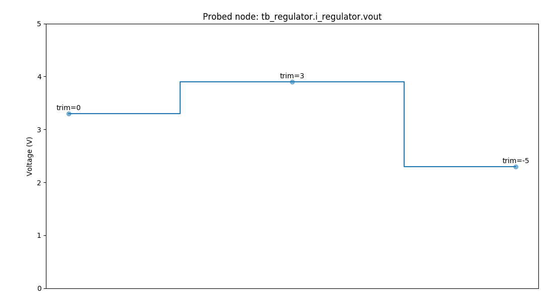
test_regulator_plot
The testcase first sets a vdd voltage and three different trim values,
saving the resulting output voltage vout for each.
The saved data is written as a PNG file containing a graph.
Note
This testcase depends on matplotlib.
To run this testcase, call:
make SIM=xcelium TOPLEVEL=tb_regulator MODULE=test_regulator_plot
test_regulator_trim
This testcase runs an automatic trimming routine find_trim_val()
to find the best trim value for a given target voltage.
The determined trim value and the resulting regulator output voltage
are printed to the console.
0.00ns INFO     Running trimming algorithm for target voltage 3.013 V
3.00ns INFO     Best trimming value is -1 --> voltage is 3.1 V (difference to target is 0.087 V)
Note that the output voltage does not exactly hit the target value because of the discrete nature of the trim steps.
To run this testcase, call:
make SIM=xcelium TOPLEVEL=tb_regulator MODULE=test_regulator_trim