The cocotb rescap Testbench
New in version 1.5.
This is the testbench test_rescap for the design rescap showing
how cocotb can be used in an analog-mixed signal (AMS) simulation.
Note
The analog probe module used in this testcase is currently only implemented for the Cadence Incisive and Xcelium simulators (with the AMS option available). Help is appreciated to provide equivalent modules for other simulators.
Overview Schematic

The Design
The design consists of a resistor and capacitor model (both written in Verilog-AMS) connected in series in a SystemVerilog module:
// the design-under-test
module rescap(input  interconnect vdd,
              output interconnect vout,
              input  interconnect vss);

  resistor
    #(.resistance (1e5))
  i_resistor
    (
     .p (vdd),
     .n (vout)
     );

  capacitor
    #(.capacitance (1e-12))
  i_capacitor
    (
     .p (vout),
     .n (vss)
     );

endmodule
The Testbench
The testbench consists of both an HDL part and a Python/cocotb part. While having HDL as part of the testbench is not common with cocotb, it is perfectly possible.
The HDL part of the Testbench
The testbench HDL part is written in SystemVerilog and instantiates the design described above
as i_rescap.
It also contains a probe module for analog values as instance i_analog_probe —
imagine this being a multimeter that you quickly connect to different nodes in the design,
measuring either voltage or current.
import nettypes_pkg::*;

module tb_rescap;

  voltage_net vdd, vss;
  real vdd_val, vss_val = 0.0;

  assign vdd = vdd_val;
  assign vss = vss_val;

  interconnect vout;

  // the design
  rescap i_rescap (.vdd  (vdd),
                   .vout (vout),
                   .vss  (vss)
                   );

  // the "multimeter"
  analog_probe i_analog_probe ();

endmodule
The probe module can capture voltage and current of a node specified by node_to_probe
(a string in this module containing a hierarchical path).
The capturing occurs whenever there is an edge on the logic signals
probe_voltage_toggle or probe_current_toggle.
The captured values can be read on real-value signals voltage and current in this module.
Here is the capture code for voltage with the “user-interface” highlighted:
var string node_to_probe = "<unassigned>";

logic probe_voltage_toggle = 0;
real voltage;

always @(probe_voltage_toggle) begin: probe_voltage
  if ($cds_analog_is_valid(node_to_probe, "potential")) begin
    voltage = $cds_get_analog_value(node_to_probe, "potential");
    // $display("%m: node_to_probe=%s has voltage of %e V", node_to_probe, voltage);
  end else begin
    voltage = 1.234567;
    $display("%m: Warning: node_to_probe=%s is not valid for $cds_get_analog_value, returning %f V",
             node_to_probe, voltage);
  end
end  // probe_voltage
The cocotb part of the Testbench
test_rescap_minimalist
This is a very minimalist testcase. To run it, call:
make SIM=xcelium TOPLEVEL=tb_rescap MODULE=test_rescap_minimalist
The testcase supplies vdd,
measures some pairs of voltage and current at vout
(same as the p terminal of the capacitor),
spaced 50 ns apart,
and prints the values as shown below.
 50.00ns INFO     tb_hdl.i_analog_probe@tb_rescap.i_rescap.vout=2.03e-14 V  -2.996e-07 A
100.00ns INFO     tb_hdl.i_analog_probe@tb_rescap.i_rescap.vout=3.029 V  2.67e-18 A
150.00ns INFO     tb_hdl.i_analog_probe@tb_rescap.i_rescap.vout=4.862 V  3.574e-18 A
200.00ns INFO     tb_hdl.i_analog_probe@tb_rescap.i_rescap.vout=5.975 V  6.285e-18 A
250.00ns INFO     tb_hdl.i_analog_probe@tb_rescap.i_rescap.vout=6.652 V  6.171e-18 A
300.01ns INFO     tb_hdl.i_analog_probe@tb_rescap.i_rescap.vout=7.063 V  6.033e-18 A
There is no current flowing out of the vout terminal,
so the current measurement always yields zero
(within the accuracy of the analog solver).
test_rescap
This is a more advanced testcase.
Note
This testcase depends on matplotlib.
The cocotb part of the testbench provides functions to:
do the sampling of voltage and current of a given node (
get_sample_data()),plot the sampled data to a file (
plot_data()).
The testcase supplies first a positive voltage to the circuit at vdd, followed by a negative voltage,
thus charging the capacitor in opposite directions.
The following graph shows the charge curve.
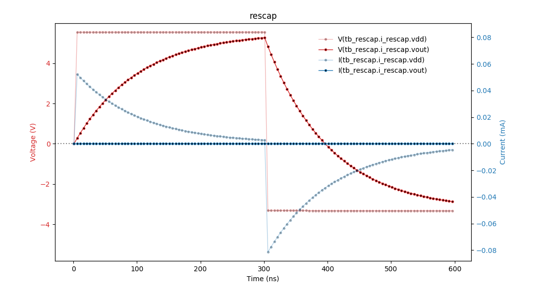
There is no current flowing out of this output voltage terminal, so the current measurement always yields zero.
To run this testcase, call:
make SIM=xcelium TOPLEVEL=tb_rescap MODULE=test_rescap